Content
Die casting molds are the foundation of precision metal part production. The mold directly determines part accuracy, surface finish, and production efficiency — making it the single most critical investment in any die casting project. Whether you're prototyping a new component or running high-volume automotive parts, understanding mold types, design processes, and key selection factors will save time, cost, and rework down the line.
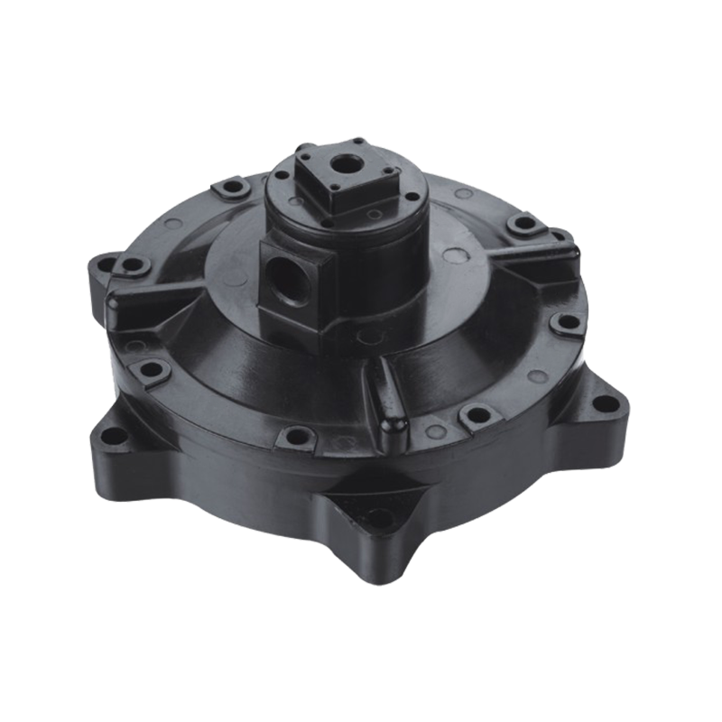
In die casting, molten metal — typically aluminum, zinc, or magnesium — is injected into a steel mold under high pressure (often 10,000–30,000 psi). The mold cavity defines every geometric detail of the final part. A poorly designed mold leads to defects like porosity, cold shuts, shrinkage, and dimensional inconsistency, all of which drive up scrap rates and delay production.
A well-engineered mold, by contrast, can deliver:
In short, the mold is not a cost center — it is the enabler of quality, repeatability, and profitability across the entire production run.
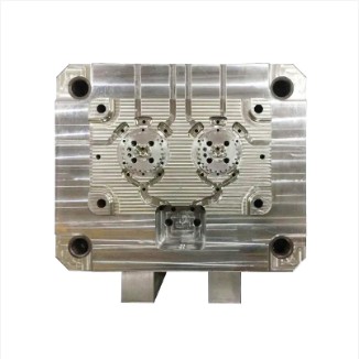
A die casting mold is a complex assembly. Understanding each component's role helps engineers optimize both mold design and process parameters.
| Component | Function | Typical Material |
|---|---|---|
| Cover Die (Fixed Half) | Holds the sprue and gate system; remains stationary | H13 Tool Steel |
| Ejector Die (Moving Half) | Opens for part ejection; houses ejector pins | H13 Tool Steel |
| Cores & Inserts | Form internal features, holes, undercuts | H13, P20, or carbide |
| Runner & Gate System | Channels molten metal into the cavity | Integral to die block |
| Ejector Pins | Push the solidified part out of the cavity | Hardened steel |
| Cooling Channels | Control solidification rate and cycle time | Drilled into die block |
| Vents & Overflows | Release trapped air and excess metal to reduce porosity | Integral to die |
Cooling channel design is particularly influential — uniform cooling reduces warpage and cuts cycle time by 15–30% compared to unoptimized layouts.
Selecting the right mold type depends on production volume, part complexity, budget, and lead time requirements. There are five primary categories used across the industry.
Prototyping dies are low-cost, single-cavity tools used to validate part geometry and function before committing to production tooling. They are typically machined from aluminum or soft steel (P20), which reduces cost and lead time. Lead times are often 2–4 weeks, and tooling costs range from $1,500 to $10,000 depending on complexity. Expected shot life is limited — usually under 1,000 shots — making them suitable only for design verification, not commercial production.
Rapid tooling bridges the gap between prototype and full production. Using advanced CNC machining and sometimes metal 3D printing for inserts, these dies can be ready in as little as 1–3 weeks. They support short production runs of 500 to 5,000 parts, making them ideal for market testing, bridge production, or low-volume specialty components. Material choices include semi-hardened P20 or H13 for improved durability.
Production dies are the workhorse of high-volume die casting. Manufactured from fully hardened H13 tool steel (HRC 44–48), they withstand 100,000 to 1,000,000+ injection cycles depending on alloy and process conditions. These molds may feature multiple cavities (2-, 4-, 8-cavity configurations) to maximize throughput. Investment is significant — typically $20,000 to $150,000+ — but the per-part cost drops dramatically at scale. A well-maintained production die for an automotive bracket might produce 500,000 parts over its lifetime.
Unit dies use a standardized master holder (the "master unit die" or MUD frame) into which interchangeable inserts are placed. This approach reduces tooling cost when a company produces multiple part variants, since only the cavity inserts need to be replaced, not the entire mold base. Insert changeover can take under 30 minutes, making this system highly flexible for contract manufacturers or companies with diverse product lines. Unit die inserts typically cost 30–50% less than equivalent standalone tooling.
Trim dies are secondary tools used to remove flash, runners, and gates from cast parts after ejection. While not involved in the casting process itself, a poorly designed trim die can damage part edges or leave residual material that requires additional finishing. Trim dies are typically made from tool steel and designed to match the parting line geometry of the casting die. For high-volume applications, hydraulic trim presses with automated trim dies can process parts in under 5 seconds per cycle.
Effective mold design follows a structured engineering process. Skipping steps — particularly simulation — is one of the most common causes of costly mold rework.
The preliminary phase begins with a thorough Design for Manufacturability (DFM) review. Engineers analyze the 3D CAD model for draft angles (typically 1–3° for external surfaces, 2–5° for internal surfaces), wall thickness uniformity (recommended 2–4 mm for aluminum), undercuts requiring side actions, and parting line placement. Early DFM feedback prevents downstream tool modifications that can cost 10–50× more to fix after steel is cut.
Calculating the projected area of the part (viewed perpendicular to the parting line) is essential for selecting the correct machine tonnage. The clamping force must exceed the injection pressure multiplied by the projected area. A typical aluminum casting at 10,000 psi injection pressure over a 200 cm² projected area requires approximately 200 tonnes of clamping force — plus a safety margin of 10–20%. Undersizing the machine causes flash; oversizing wastes energy and machine capacity.
Die volume and block size are determined by the part envelope, wall thickness requirements, placement of cooling channels, and structural integrity of the mold under cyclic loading. Mold designers calculate the minimum steel thickness between the cavity and the mold boundary — typically at least 30–50 mm — to prevent die cracking under injection pressure. Complex geometries may require multi-piece inserts or lifters to avoid undercuts.
Modern die casting simulation software (such as MAGMASOFT, ProCAST, or Flow-3D) combines computational fluid dynamics (CFD) with semi-empirical thermal and rheological models. These tools predict:
Studies show that simulation reduces physical mold trials by 40–60%, significantly compressing time-to-production. Jieda integrates CAD/CAM/CAE software as standard practice in all mold design workflows.
Beyond the basic design steps, several critical factors separate average tooling from exceptional tooling:
H13 hot-work tool steel is the industry standard for aluminum die casting molds due to its excellent thermal fatigue resistance, toughness, and hardenability. For zinc alloys, P20 is often sufficient. The mold material must withstand repeated thermal cycling from ambient temperature to 600–700°C (at the cavity surface) without cracking. Premium H13 grades with tighter composition control (e.g., ESR-refined H13) can extend tool life by 20–40%.
The gate is the narrowest point where molten metal enters the cavity, typically 1–3 mm thick for aluminum. Gate velocity must be controlled (typically 30–60 m/s) to prevent jetting, premature solidification, or erosion of the die steel. Fan gates distribute flow evenly for flat parts; tangential gates suit cylindrical geometries. Runner cross-sections should be trapezoidal to maximize heat retention and minimize pressure drop.
Cooling circuit layout directly affects cycle time, part quality, and die life. Conformal cooling — where channels follow the cavity contour — is increasingly used for complex geometries and can reduce hot spots by up to 40% compared to straight-drilled channels. Die temperature should be maintained at 150–250°C for aluminum to balance fill speed and solidification rate. Temperature sensors embedded in the mold enable real-time feedback control.
Nitriding the cavity surface (to a depth of 0.1–0.2 mm, HV 900–1100) reduces soldering (aluminum sticking to the die) and improves wear resistance. PVD coatings such as CrN or TiAlN can further extend surface life. Release agents — sprayed as a thin film each cycle — must be compatible with the alloy and part geometry to prevent buildup.
Insufficient draft causes part sticking, ejector pin marks, and surface damage. For textured surfaces, draft must increase by approximately 1° per 0.025 mm of texture depth. Ejector pin placement should be at robust part features to prevent deformation during ejection. Stripper plates are preferred for thin-walled or fragile parts.
Inadequate venting is a primary cause of porosity and surface blistering. Vent channels of 0.05–0.15 mm depth should be placed at the last-fill areas of the cavity. Overflow wells — small reservoirs connected to the cavity — capture cold metal and air from the initial fill front, significantly improving surface and structural quality of the final part.

Ningbo Jieda Molding & Machine Co., Ltd. has been manufacturing aluminum die casting molds and precision die cast parts since 1987, accumulating over three decades of engineering expertise. Headquartered in Beilun, Ningbo — widely recognized as China's "Hometown of Die-casting Molds" — Jieda operates from a 12,000 m² facility with fixed assets exceeding 70 million RMB.
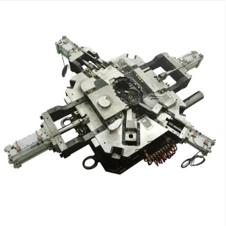
The company's equipment fleet includes more than 80 machines: precision CNC machining centers, CNC EDM, wire cutting, mold clamping machines, and Hong Kong Lijin automatic die-casting machines at 200T, 280T, 400T, 500T, 800T, and 1600T clamping force — enabling production of components ranging from small connectors to large structural castings.
Jieda's engineering workflow integrates PRO/E CAD, CAM, and CAE simulation tools throughout the mold design process, aligning with the best practices described throughout this article. The company holds IATF16949 quality management system certification, with a closed-loop management model covering risk prevention, goal clarity, process definition, objective data, and continuous improvement.
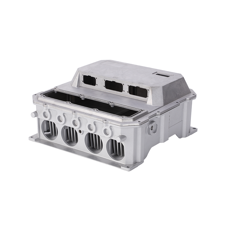
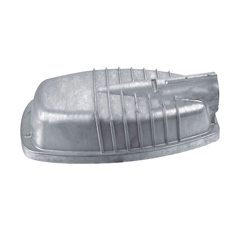
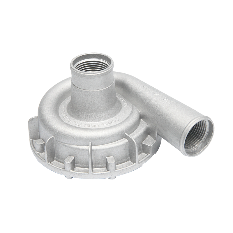
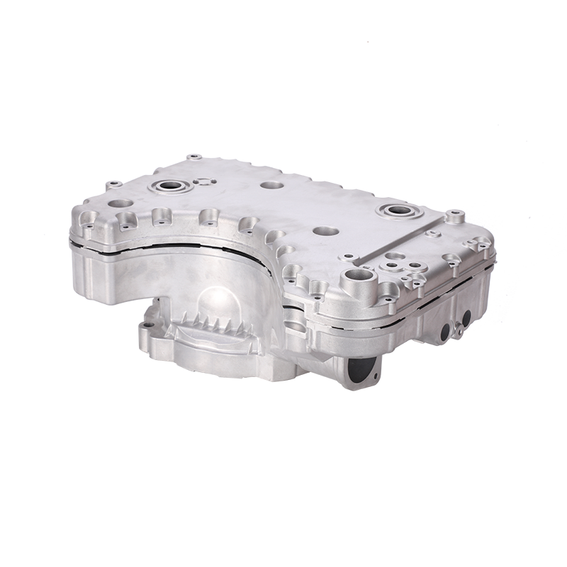
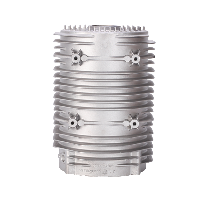
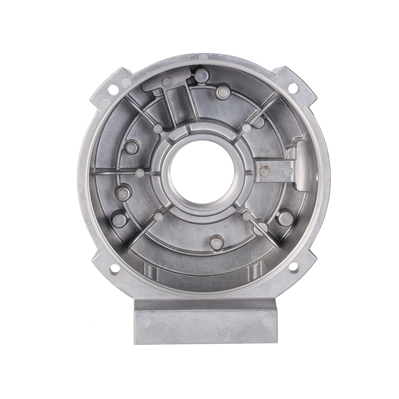
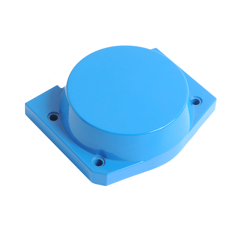
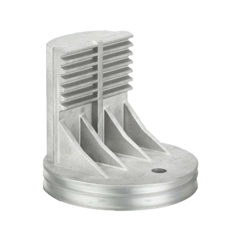
Product categories include automotive accessories, motor housings, pneumatic components, communication equipment enclosures, reducer housings, new energy photovoltaic components, and lighting fixtures. Parts are exported to the United States, Germany, Italy, the UK, France, Poland, Finland, India, Australia, and other markets — consistently earning high praise for dimensional accuracy, surface finish, and on-time delivery. Jieda is recognized as a key mold enterprise in Beilun District, Ningbo.
For aluminum alloys, a properly maintained H13 steel production die typically lasts 100,000 to 500,000 shots. Zinc dies can exceed 1,000,000 cycles due to lower casting temperatures. Mold life depends heavily on material choice, cooling design, surface treatment, and preventive maintenance schedules.
Lead times for production tooling range from 6 to 14 weeks depending on part complexity, number of cavities, and the manufacturer's capacity. Prototyping and rapid tooling dies can be completed in 2–4 weeks. Providing complete and finalized 3D CAD data at the project start is the single most effective way to compress lead time.
The most commonly used alloys in die casting are aluminum (e.g., A380, ADC12), zinc (ZA-8, Zamak series), magnesium (AZ91D), and copper-based alloys. Aluminum is the most prevalent, accounting for approximately 80% of all die cast parts by weight globally. Each alloy imposes different thermal and chemical demands on the mold material and surface treatment.
Yes. Common repair techniques include TIG welding with compatible filler rods, laser welding for precision repairs, and re-machining of worn surfaces. Preventive maintenance — polishing, re-nitriding, and cooling channel flushing every 20,000–50,000 shots — significantly reduces unplanned repair costs and extends overall mold service life.
MOQ varies by manufacturer and part complexity. For custom production tooling projects, many manufacturers — including Jieda — can accommodate orders starting from a few hundred parts once tooling is completed, with pricing structured to reflect tooling amortization. High-volume programs are priced separately from low-volume or NPI (new product introduction) projects.
ARE YOU READY TO COOPERATE WITH jieda?
* Your email is safe with us, we don’t spam.
PRODUCTS
CONTACT INFO
nbjd011@126.com
+86-574-86115705
No. 58 Mould Road, Daqi Technology Industrial Zone, Beilun District, Ningbo
 English
 Español
 italiano