English
 Español
 italiano
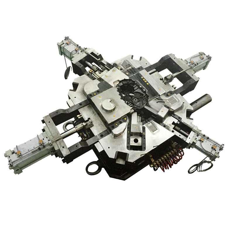
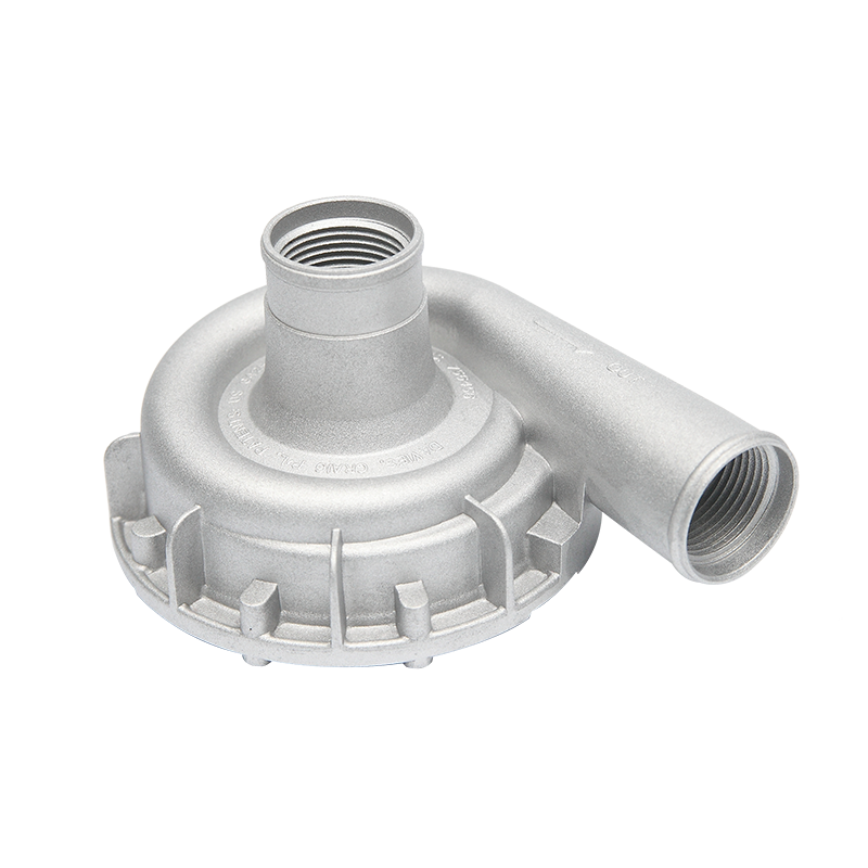
What is a Die Casting Mold?
A die casting mold is a precision-engineered metal tool that shapes molten metal under high pressure (typically 1,500 to 25,000 psi) into complex, net-shape components with tolerances as tight as ±0.002 inches (±0.05 mm). It serves as the critical interface between the die casting machine and the final product, determining part quality, dimensional accuracy, and production efficiency.
Unlike sand casting or investment casting, die casting molds are reusable tools that can produce 100,000 to 1,000,000+ shots before requiring replacement, depending on the material and design. The mold consists of two halves—the stationary cover die and the movable ejector die—that close to form a cavity matching the desired part geometry.
Key Characteristics
- Material: Premium-grade tool steels such as H13 (1.2344), 8407, or DIEVAR, heat-treated to 44-48 HRC for optimal balance of hardness and toughness.
- Operating Temperature: Cavity surface temperatures range from 300°F to 500°F (150°C to 260°C) for aluminum, and up to 700°F (370°C) for zinc alloys.
- Cycle Time: Typical production cycles range from 30 seconds to 2 minutes, enabling high-volume manufacturing of 500-2,000 shots per day.
Core Structural Components of a Die Casting Mold
The functional integrity of a die casting mold relies on six essential component systems working in concert. Each component addresses specific thermal, mechanical, and operational challenges inherent in high-pressure metal injection.
| Component | Function | Critical Specifications |
|---|---|---|
| Cavity & Cores | Define part geometry and internal features | Tolerance: ±0.001 in; Surface finish: 16-32 μin Ra |
| Sprue Bushing | Channel molten metal from the machine nozzle | Hardened to 50-52 HRC; 3-5° draft angle |
| Runner System | Distribute metal to cavity gates | Trapezoidal cross-section; Velocity: 30-60 m/s |
| Cooling Channels | Regulate thermal balance and solidification | Diameter: 8-12mm; Distance from cavity: 1.5-3× diameter |
| Ejector System | Remove solidified casting from the mold | Pin diameter: 3-8mm; 1-3° taper; 20-30 pins typical |
| Venting System | Expel air and prevent gas porosity | Depth: 0.05-0.15mm; Total vent area: 20-30% of gate area |
Thermal Management Architecture
The cooling channel network represents the most complex design challenge. Improper cooling causes 60-70% of mold-related quality defects. Modern molds employ conformal cooling channels that follow cavity contours, reducing cycle times by 20-40% compared to traditional straight-drilled channels. For example, a transmission housing mold with conformal cooling achieved a cycle time reduction from 85 seconds to 52 seconds while improving dimensional consistency by 35%.
Common Defects and Troubleshooting
Approximately 85% of die casting defects originate from mold-related issues rather than machine parameters or material quality. Understanding root causes enables rapid diagnosis and corrective action.
Porosity and Gas Entrapment
Porosity levels exceeding 3-5% by volume typically render parts unacceptable for structural applications. Root causes include inadequate venting (vents clogged with lubricant residue or aluminum buildup), excessive injection velocity causing turbulence, and poor gating design creating air pockets. Troubleshooting steps: increase vent depth to 0.10-0.15mm, reduce plunger speed from 4 m/s to 2.5 m/s during cavity fill phase, and relocate gates to avoid entrapped air zones.
Cold Shut and Flow Marks
Cold shuts occur when two metal fronts meet below fusion temperature (approximately 1,100°F/593°C for aluminum). Increasing mold temperature by 50°F (28°C) often eliminates cold shuts without parameter changes. Ensure cooling channels maintain ±5°F (±3°C) uniformity across the cavity surface. Flow marks indicate premature solidification; solutions include increasing metal temperature by 25-50°F (14-28°C) or enlarging gate thickness by 0.5-1.0mm.
Dimensional Inaccuracy
Aluminum alloys shrink 4.5-5.5% during solidification; zinc alloys shrink 0.6-0.8%. Mold designers must compensate with shrinkage allowances precisely calibrated to alloy composition. For example, A380 aluminum requires 5.0% linear shrinkage compensation, while Zamak 3 zinc requires only 0.7%. Dimensional drift during production often indicates thermal imbalance—verify cooling channel flow rates exceed 2 gallons per minute (7.6 L/min) per circuit.
Why Molds Develop Burrs and Cracks
Burrs (flash) and cracks represent the two most costly mold failure modes, accounting for 45% of unplanned mold maintenance. Understanding their metallurgical and mechanical origins is essential for prevention.
Mechanism of Burr Formation
Burrs form when molten metal penetrates gaps between mating surfaces exceeding 0.05mm (0.002 inches). Flash thickness increases exponentially with gap size: a 0.10mm gap produces flash 4× thicker than a 0.05mm gap. Primary causes include:
- Clamping force deficiency: Insufficient machine tonnage allows mold separation. Required clamping force = projected part area (in²) × injection pressure (psi) × safety factor (1.2-1.5).
- Parting line wear: After 50,000-100,000 cycles, parting line surfaces develop micro-erosion from thermal cycling and abrasive metal flow, creating leak paths.
- Thermal distortion: Uneven heating causes 0.02-0.08mm bowing in large molds (over 20 inches), opening gaps at corners.
Crack Propagation Dynamics
Heat checking (thermal fatigue cracking) initiates after 5,000-20,000 cycles in high-heat zones and propagates at 0.1-0.5mm per 1,000 cycles. The mechanism involves cyclic thermal stresses: cavity surfaces heat to 600-800°F (315-427°C) during injection, then quench to 300-400°F (150-200°C) during cooling. This 300-400°F temperature swing induces compressive stress during heating and tensile stress during cooling, exceeding the material's fatigue limit.
Crack locations concentrate in:
- Sharp internal corners (stress concentration factor Kt > 3.0)
- Gate areas experiencing direct molten metal impingement at 30-60 m/s velocity
- Thin-walled sections (<3mm) with rapid heat extraction
- Ejector pin holes are creating stress risers
Extending Die Casting Mold Service Life
Implementing comprehensive life-extension strategies can increase mold longevity from 100,000 shots to 300,000+ shots, reducing per-part tooling costs by 60-70%.
Material Selection and Heat Treatment
Premium H13 steel with electro-slag remelting (ESR) reduces non-metallic inclusions by 90%, extending crack initiation life by 40%. Optimize heat treatment to achieve 46-48 HRC hardness with 12-14% retained austenite for optimal toughness. Ion nitriding to 0.15-0.25mm depth increases surface hardness to 65-70 HRC, resisting erosion while maintaining ductile substrate.
Thermal Management Protocols
Maintain cavity surface temperature within ±15°F (±8°C) of target using closed-loop cooling control. Implementing pulse-cooling (intermittent coolant flow) reduces thermal shock by 30% compared to continuous flow. Preheat molds to 250-350°F (120-175°C) before production to minimize initial thermal shock; starting "cold" reduces expected life by 25-30%.
Maintenance and Surface Engineering
Scheduled maintenance every 10,000-15,000 shots prevents catastrophic failures. Key practices include:
- Crack arresting: Grind out heat-check cracks exceeding 0.5mm depth and repair with TIG welding using matching filler material, followed by stress-relief tempering at 25°F (14°C) below original tempering temperature.
- Surface coatings: Physical vapor deposition (PVD) coatings of TiAlN or CrN (2-4 μm thickness) reduce aluminum soldering by 80% and extend polish intervals from 5,000 to 15,000 shots.
- Lubrication optimization: Apply water-based lubricants at a 1:80-1:120 dilution ratio; excessive lubricant causes buildup and porosity, while insufficient application accelerates erosion.
Design for Longevity
Design decisions determine 70% of mold life potential. Critical guidelines:
- Maintain a minimum 1.5mm radius on all internal corners (reduces stress concentration by 60%)
- Limit core length-to-diameter ratios to 4:1 to prevent deflection-induced flash
- Position cooling channels 1.5-2.0× diameter from cavity surface for optimal heat extraction without structural weakening
FAQ about Die Casting Molds
What is the typical cost range for a die casting mold?
Die casting mold costs range from $15,000 for simple zinc parts to $250,000+ for complex automotive transmission cases. Aluminum molds typically cost 20-30% more than zinc molds due to higher thermal stresses requiring more robust construction. Prototype molds using P20 steel (instead of H13) reduce initial costs by 40-50% but limit production to 10,000-20,000 shots.
How long does it take to manufacture a die casting mold?
Standard mold lead times are 8-16 weeks, depending on complexity: simple two-plate molds require 6-8 weeks, while complex slides and unscrewing mechanisms extend timelines to 14-20 weeks. Rush programs using parallel machining operations can reduce this by 30-40% at a 15-25% cost premium.
Can die-casting molds be modified after initial production?
Modifications are feasible but costly: welding and re-machining cavity surfaces cost 15-25% of the original mold price, while adding slides or changing parting lines often exceeds 50% of the initial cost. Design for change (removable inserts) allows geometry updates at 5-10% of mold cost. Plan for 2-3 engineering change orders (ECOs) during the product lifecycle.
What is the difference between conventional and vacuum die casting molds?
Vacuum die casting molds include sealed parting lines and venting systems capable of achieving <50 mbar cavity pressure, reducing porosity from 3-5% to <1% and enabling heat-treatable castings. Additional costs include vacuum valves ($2,000-5,000), sealed ejector systems, and precise machining tolerances (±0.01mm on parting surfaces). Vacuum molds are essential for structural automotive components requiring T6 heat treatment.
How do you determine when a mold has reached end-of-life?
End-of-life criteria include: dimensional drift exceeding tolerance bands (typically ±0.005 inches), crack density exceeding 5 cracks per square inch in critical areas, or repair costs exceeding 40% of replacement cost. Many molds undergo 3-5 major refurbishments (welding, re-machining, re-nitriding) before retirement, extending total life to 500,000+ shots. Track cumulative repair costs; when annual maintenance exceeds the depreciation of a new mold, replacement is economically justified.