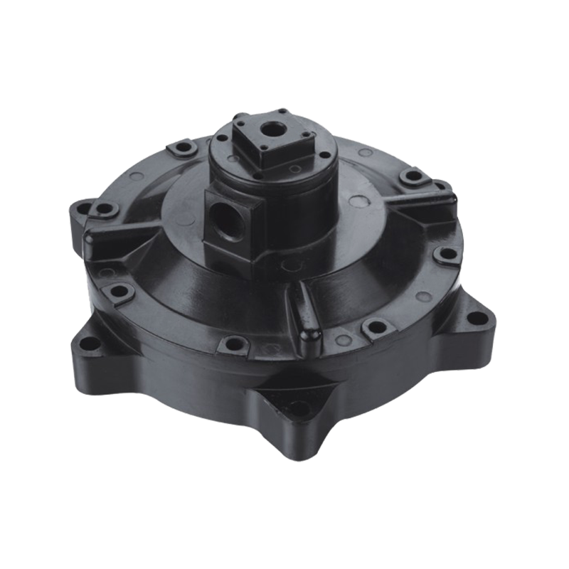
Content
A die casting mold project can look complete on screen and still fail in the first trial: cold shuts, soldering, or porosity appear in areas that seemed perfectly designed. In our experience, the problem is rarely a single toolpath or a single dimension. It is usually a chain of decisions made before steel is cut. For this reason, we treat CAD, CAM, and CAE as one connected workflow, not three separate operations. The conclusion is simple: if you want consistent die casting quality, the mold design phase must include shrink-scale modeling, fill and solidification simulation, and CAM verification before production begins.
Before opening a CAD file, a designer needs a clear set of design targets. These targets become the basis for cavity dimensions, gating, cooling, and ejection. The table below summarizes typical ranges used for aluminum die casting molds.
| Parameter | Typical Range | Effect on Mold Design |
|---|---|---|
| Alloy shrinkage | 0.5–0.7% | Determines cavity scaling and final core dimensions |
| Draft angle | 1° external, 1.5–2° internal | Controls ejection, surface damage, and die wear |
| Wall thickness | 1.5–4 mm for common aluminum parts | Balances fill, strength, and cooling time |
| Parting line | Placed at the largest cross-section | Affects flash, trim, and mold construction complexity |
| Cooling channels | Uniform layout with controlled spacing | Reduces hot spots and shrinkage porosity |
These values are starting points, not fixed rules. A CAE model can refine them for a specific part. When a buyer asks for exactly this geometry, the mold designer should still apply these fundamentals, because the die casting process will amplify any design weakness. Changing shrinkage after the cavity is cut means starting over, so the design review must include alloy grade, part weight, wall section, surface texture, and casting machine capacity before any CAM work begins.
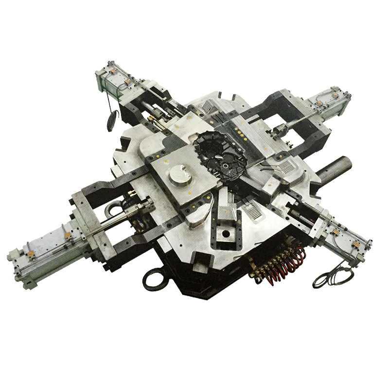
CAD work for a die casting mold starts with a part model that has already been reviewed for draft, radii, and uniform wall thickness. The designer then applies shrinkage scaling to the cavity, creates the parting surface, separates core and cavity, and adds slides, lifters, inserts, or cooling channel positions. Without this structured order, a mold can have gaps at the parting line or die lock conditions that are difficult to correct later.
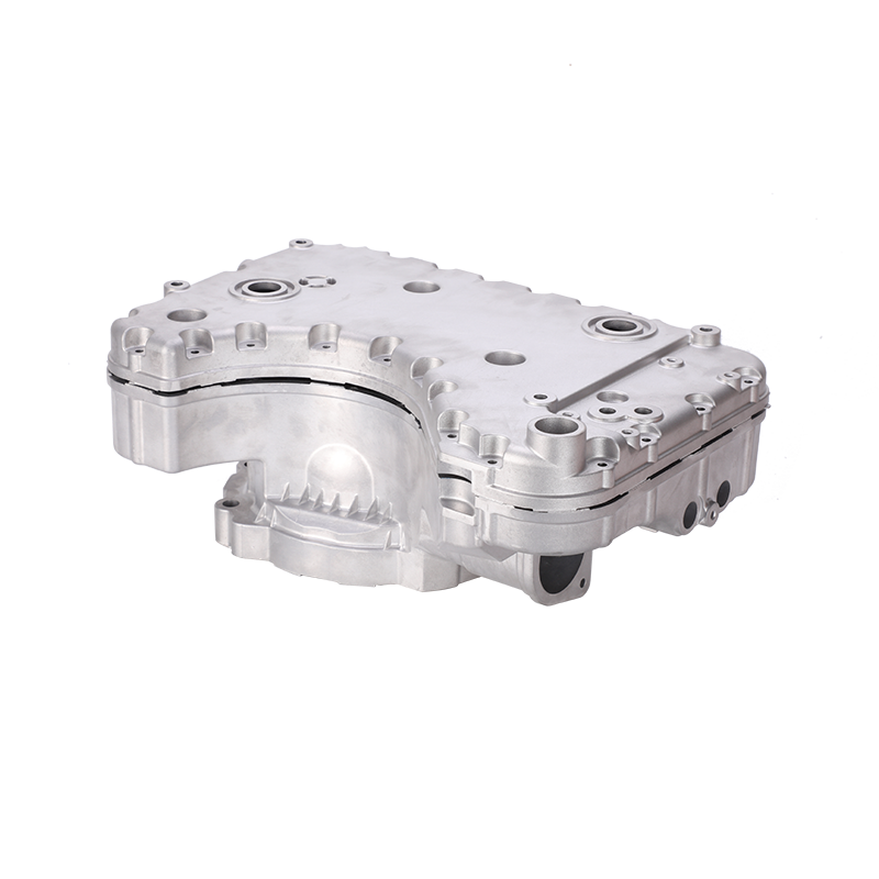
CAD geometry is commonly exchanged in STEP or IGES format with the customer, but the mold design model is not the same as the part model. The cavity is scaled, split, and detailed for manufacturing. For long production runs, we create assembly-level CAD that includes the complete mold base, not only the cavity. This allows interference checks, cooling line verification, and alignment control before CAM programming. We apply this workflow to our customized high-pressure aluminum die casting molds, especially for thin-wall housings with deep ribs and tight inside corners.
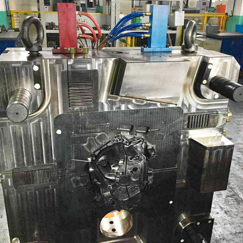 Aluminum Die Casting Molds Customized High-pressure- Ningbo Jieda Molding & MachView Product →
CAE simulation is used to predict how molten metal fills the cavity, where solidification starts, and where trapped air or shrinkage porosity may form. A good simulation does not just show a color map; it gives the design team a short list of corrections: move an overflow, change a gate, add cooling, or adjust wall thickness. Air entrapment often appears near bosses or ribs, so overflow positions must be checked before the steel is machined.
In a typical project, using CAE before CAM significantly reduces the number of physical trials. The chart below is an illustrative comparison based on common die casting mold development projects.
This reduction matters because each trial consumes alloy, machine time, and engineering hours. It also shortens the time before a mold can go into normal production. To understand one common failure in this area, see our article on whether die casting mold design can prevent metal soldering defects.
CAM translates the finished mold design into CNC programs for cavity, core, inserts, electrodes, and cooling holes. For die casting molds, critical areas such as the parting line and locking surfaces often need tolerances around ±0.02 mm. A CAM strategy must therefore choose the right tool diameter, stepover, feed rate, and finishing pass according to the surface geometry.
EDM plays an important role for deep ribs and small internal corners where a cutter cannot reach. CAM also programs the graphite or copper electrodes used in these operations. In our process, toolpath verification is performed by simulating material removal before the program reaches the CNC machine. When the alloy is a lower-temperature zinc alloy, the mold wear pattern is different, and the designer can use tighter clearances in some areas. Our customized high-precision zinc die casting molds are produced with the same CAD-CAM-CAE discipline, adapted to the material.
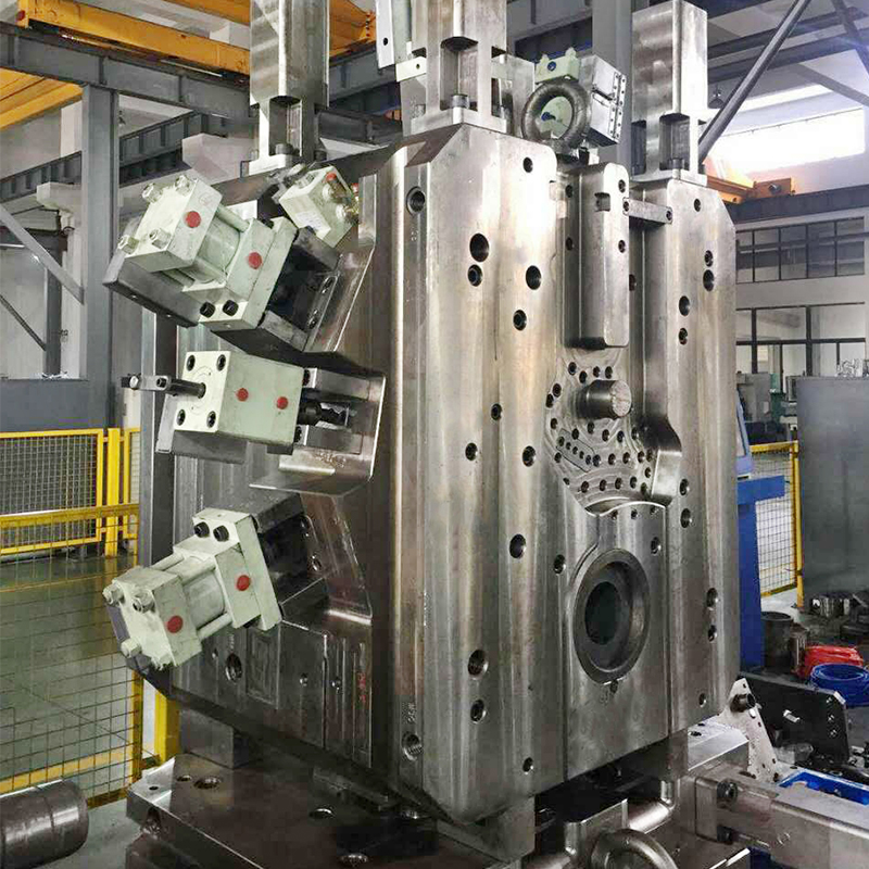 Zinc Die Casting Molds Customized High-precision- Ningbo Jieda Molding & MachineView Product →
Buyers often compare mold prices by weight or machining hours. That approach misses the biggest cost driver: rework. A typical die casting mold cost structure in an integrated process looks like this.
Design and simulation represent about 15% of the mold budget, but they influence the remaining 85%. If a mold has to be opened for a design correction, machining and trial costs rise quickly. Our quality system follows IATF 16949 and uses objective data at design reviews, so simulation results are documented rather than used only as a presentation. The line chart below shows a representative first-shot pass rate improvement when CAE is used during development.
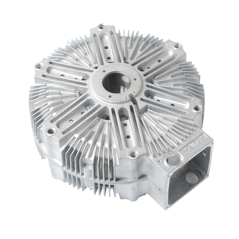
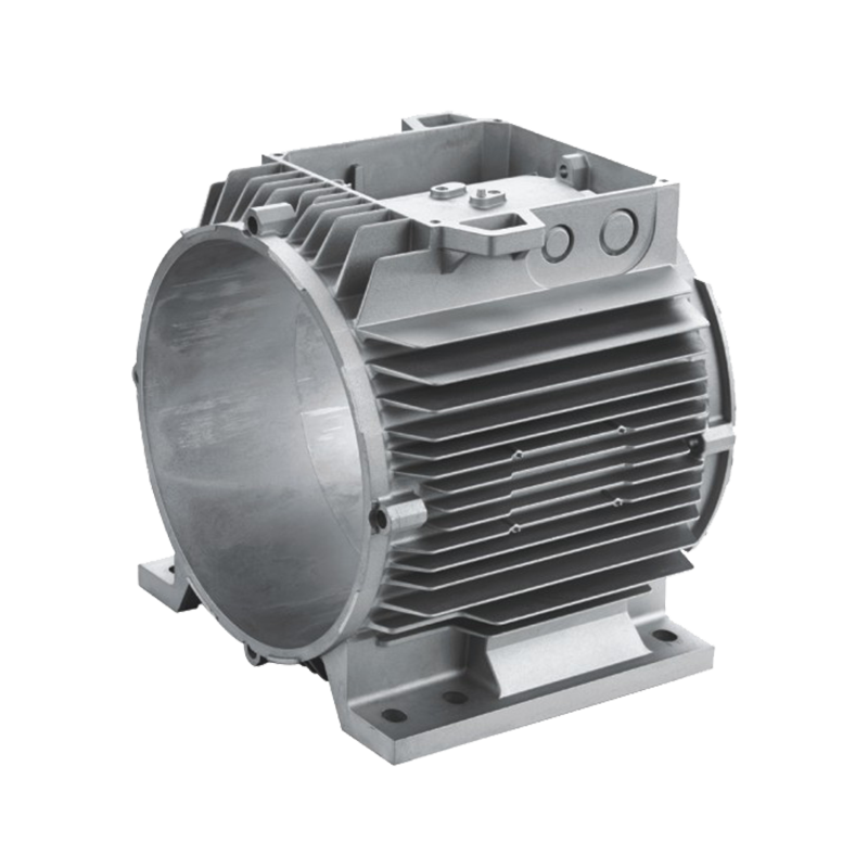
These two charts should be read together: fewer trials means lower cost, and a higher first-shot pass rate means the mold reaches stable production faster. For production parts, this discipline carries through to components such as our high-pressure aluminum die-cast automobile motor housing.
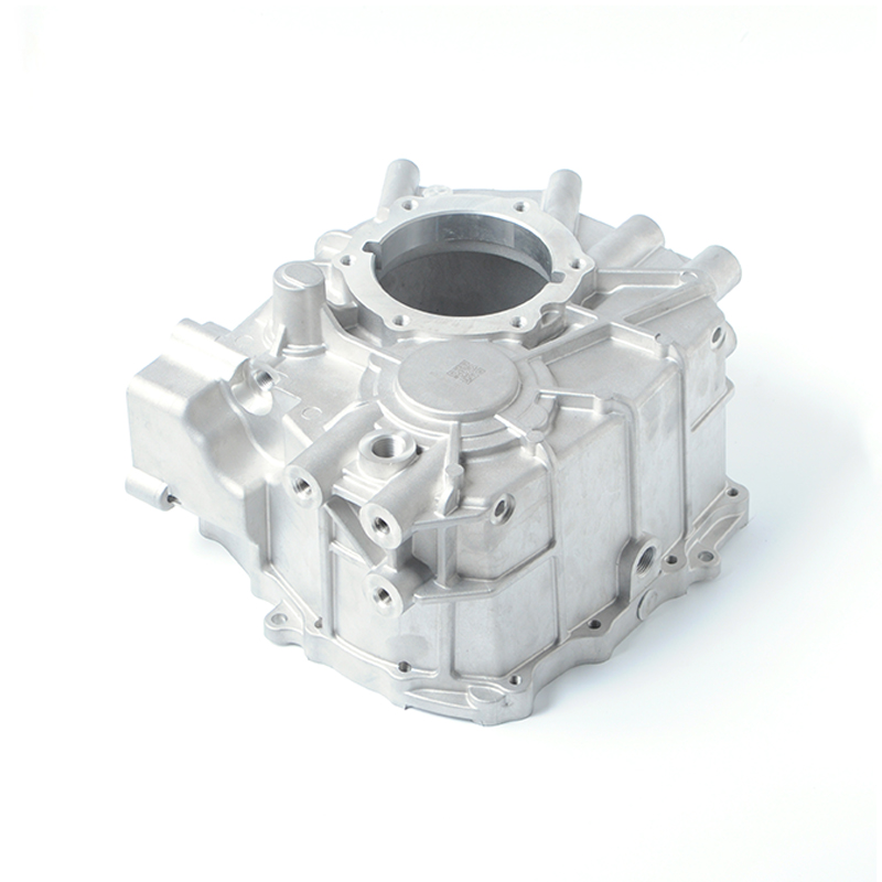 Automobile Motor Housing in High-pressure Aluminum Die Casting- Ningbo Jieda MolView Product →
For most common aluminum alloys, 0.5% to 0.7% linear shrinkage is typical, but the exact value depends on alloy, part geometry, wall thickness, and casting parameters. A CAE solidification analysis helps refine this assumption instead of relying on a fixed number.
No. CAE reduces the number of trials and the risk of major rework, but it cannot fully replace verification. It is most effective when combined with controlled casting parameters and good machining practice.
Typically 1° on external walls and 1.5° to 2° on internal walls, depending on texture and ejection direction. For textured surfaces, designers may need 2° to 3°.
CAD/CAM/CAE in die casting mold design is not about having expensive software; it is about making decisions in a disciplined order: part analysis, simulation, machining, and verification. A mold shop that uses CAE before cutting steel can catch defects earlier, deliver more reliable molds, and support production parts that meet dimensional and structural requirements.
To discuss your mold project, ask how the shop handles shrinkage analysis, fill simulation, and CAM tolerance strategy. The answers will tell you whether the tooling will arrive on time and perform in production.
ARE YOU READY TO COOPERATE WITH jieda?
* Your email is safe with us, we don’t spam.

PRODUCTS
CONTACT INFO
nbjd011@126.com
+86-574-86115705
No. 58 Mould Road, Daqi Technology Industrial Zone, Beilun District, Ningbo

 English
 Español
 italiano